

Applied projects
Remote Relay Control via Network (WiFi + LAN)

Jul
In this post, we would like to introduce a product that allows you to control a relay module through network communication. This means you can remotely turn any device on or off in your home or workplace via the network.
This project is actually a 5-channel network-based relay module that can connect to the network through both a LAN cable and Wi-Fi. It has a dedicated IP address, along with a username and password to access the module’s control panel. However, since this is an open-source project, you can set your own preferred IP address and implement any changes you need in the code. You can easily connect to the relay module using your mobile phone or computer by entering the IP address in your browser, and control each channel individually by switching it on or off.
This project is provided as open-source and you are free to develop it based on your own needs. The module is programmed using the Arduino environment, and the PCB is designed in Altium Designer. You can purchase and download the project files and documentation through the link below.
Let’s take a look at the components used in this module:
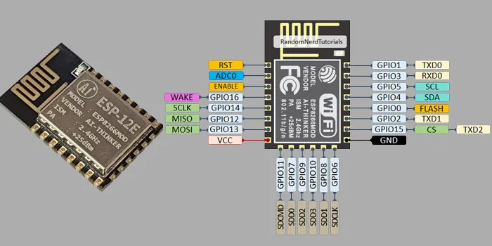
The core of this module is the ESP8266 12E microcontroller, which is one of the most widely used and powerful microcontrollers available at an affordable price. In the image below, you can see the layout and photo of the ESP8266 microcontroller used in this project.
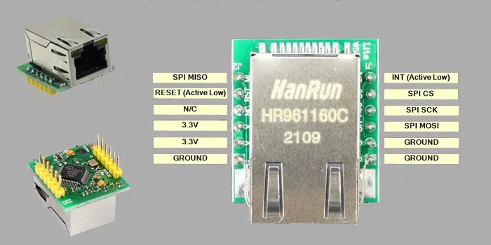
For network connectivity and LAN cable connection, the W5500 module is used, which is a highly efficient Ethernet module. Below, you can see the schematic and image of this LAN port module.
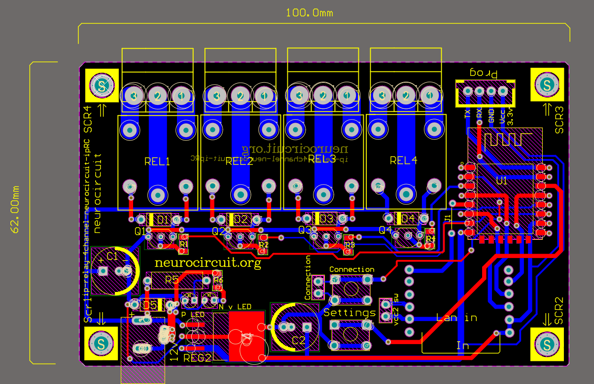
Picture of the circuit schematic
Key Features of the Project:
In the circuit design, two micro switches are included. On the board, they are labeled with the following names and their functions:
-
Settings Button: As the name suggests, this button is used for the initial setup of the module, such as configuring the username, password, and other basic settings.
-
Connection Button: This button allows you to select the type of connection you want to use with the module — either through a LAN cable or via WiFi.
The board includes a 4-pin USART socket, which you can use to program the board using a USB-to-USART programmer.
The relays selected for this module are standard 5V 10A relays. The relay section includes flyback diodes to protect the transistors. These diodes ensure that the transistors won’t get damaged during relay switching.
The circuit is protected against reverse polarity. If you connect the power supply incorrectly (reverse the positive and negative), a yellow or red LED (depending on the LED color you choose) will light up, indicating incorrect polarity. If connected correctly, a green LED will turn on.
The PCB is double-sided and includes a combination of DIP and SMD components. The components have been chosen based on their functionality, so we strongly recommend not modifying the board layout or component types.
Since this PCB is double-sided and many of its layers are connected using vias, it cannot be reliably printed using DIY methods at home. Therefore, it must be manufactured using professional PCB fabrication tools. We suggest that you leave the PCB fabrication to professional manufacturing companies.
(We ourselves are designers and producers of various electronic equipment and PCBs, and if you’re interested in mass production of this module, we’re happy to support you.)
To stabilize and manage voltage between different parts of the circuit, appropriate voltage regulators are used.
You can produce and sell this project, as it has a wide range of applications. Also, to receive future updates about this module and project, we recommend registering on our website. If any updates are released, you’ll be notified through the email you registered with.
You can purchase and download the complete files of this project below
Join our newsletter to get the latest projects, tutorials, and tech updates straight to your inbox! 🚀