
Arduino and microcontroller projects
Arduino Wave Generator Project
May
This project demonstrates how to build a multi-wave signal generator using a microcontroller, an OLED display, and simple input controls. It is designed for electronics learners who want to understand PWM signal generation, waveform visualization, and real-time embedded system interaction.
At the core of the system, different waveform types such as square, sine, triangle, and sawtooth are generated digitally using software logic. The output signal is produced through a PWM pin, allowing users to observe and experiment with different electrical wave behaviors in real time.
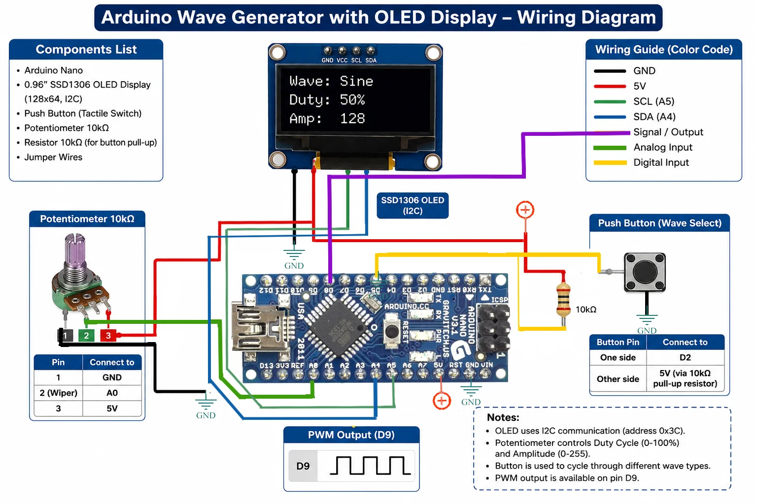
The system includes a button to switch between waveform types and a potentiometer to control both duty cycle and amplitude dynamically. This gives the user full manual control over signal characteristics, making the project highly interactive and educational.
An OLED display based on the SSD1306 driver shows real-time parameters including waveform name, duty cycle percentage, and amplitude level. This visual feedback helps users understand how input changes affect output signals instantly.
Technically, the project uses a microcontroller with ADC input for reading analog values and PWM output for signal generation. The waveform logic is implemented in software, where timing functions and mathematical operations simulate different signal shapes. For example, sine waves are generated using trigonometric functions, while square waves depend on time-based thresholds.
Get exclusive PCB projects and circuits in your inbox.
This project is ideal for students studying embedded systems, electronics engineering, and signal processing. It provides hands-on experience with analog control, digital signal generation, and display interfacing. It can also be extended into more advanced applications such as function generators, audio synthesis, or testing equipment for laboratory use.
Overall, this Arduino-based waveform generator is a powerful learning platform that combines hardware control, software logic, and real-time visualization in a compact embedded system.
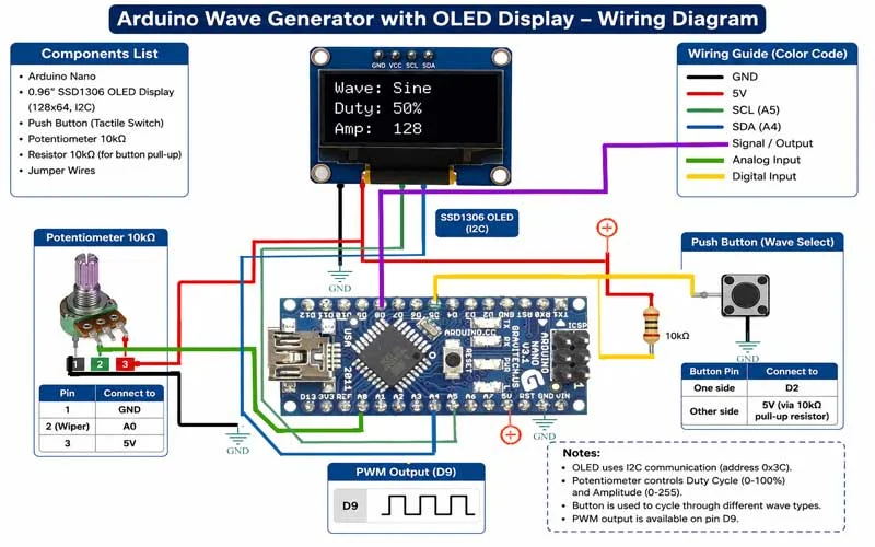
Below you can see the connection schematic.