

Robotics projects
Line-following robot with Arduino
May
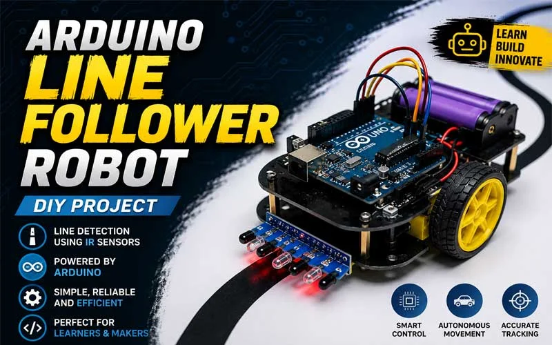
This project is a simple but effective Arduino-based line follower robot designed to detect and follow a black line on a contrasting surface using infrared (IR) sensors. The robot uses two IR sensors placed on the left and right side of the chassis to continuously read the path underneath. Based on the sensor readings, the Arduino makes real-time decisions to control the direction of the robot through a motor driver and four DC motors.
At the core of this system is an Arduino board, which acts as the brain of the robot. Two IR sensors (LS and RS) are connected to digital input pins. These sensors detect whether they are over a black line or a white surface by reflecting infrared light. When the sensor is over a dark surface, it typically reads a LOW signal, and when it is over a light surface, it reads a HIGH signal. The combination of these two sensor readings allows the robot to understand its position relative to the line.
The robot uses a motor driver module to control four DC motors, which are responsible for movement. The motors are connected in pairs: left motors (LM1, LM2) and right motors (RM1, RM2). By controlling the direction of each motor pair, the robot can move forward, stop, turn left, or turn right.
You can also see the result in the video below
Working Principle
The logic of the first version of the code is straightforward. The Arduino continuously checks the state of both sensors:
-
If both sensors detect the line (or both are off the line depending on calibration), the robot stops.
-
If neither sensor detects the line, the robot moves forward.
-
If only the left sensor detects the line, the robot turns left.
-
If only the right sensor detects the line, the robot turns right.
This simple decision-making system allows the robot to stay on track by constantly correcting its direction.
In the second version of the code, a more structured approach is introduced using a switch-case statement. Here, the sensor inputs are first read into variables, and then a function determines the robot’s state (such as forward, left, right, stop). Each case represents a different movement condition, and the motor outputs are controlled accordingly. This modular design makes the code cleaner and easier to expand or debug in more complex projects.
Hardware Used
-
Arduino Uno or Nano (or compatible board)
-
2 × IR sensors (left and right line detection)
-
L298N motor driver module (or similar H-bridge driver)
-
4 × DC motors (differential drive system)
-
Robot chassis and wheels
-
Power supply (battery pack)
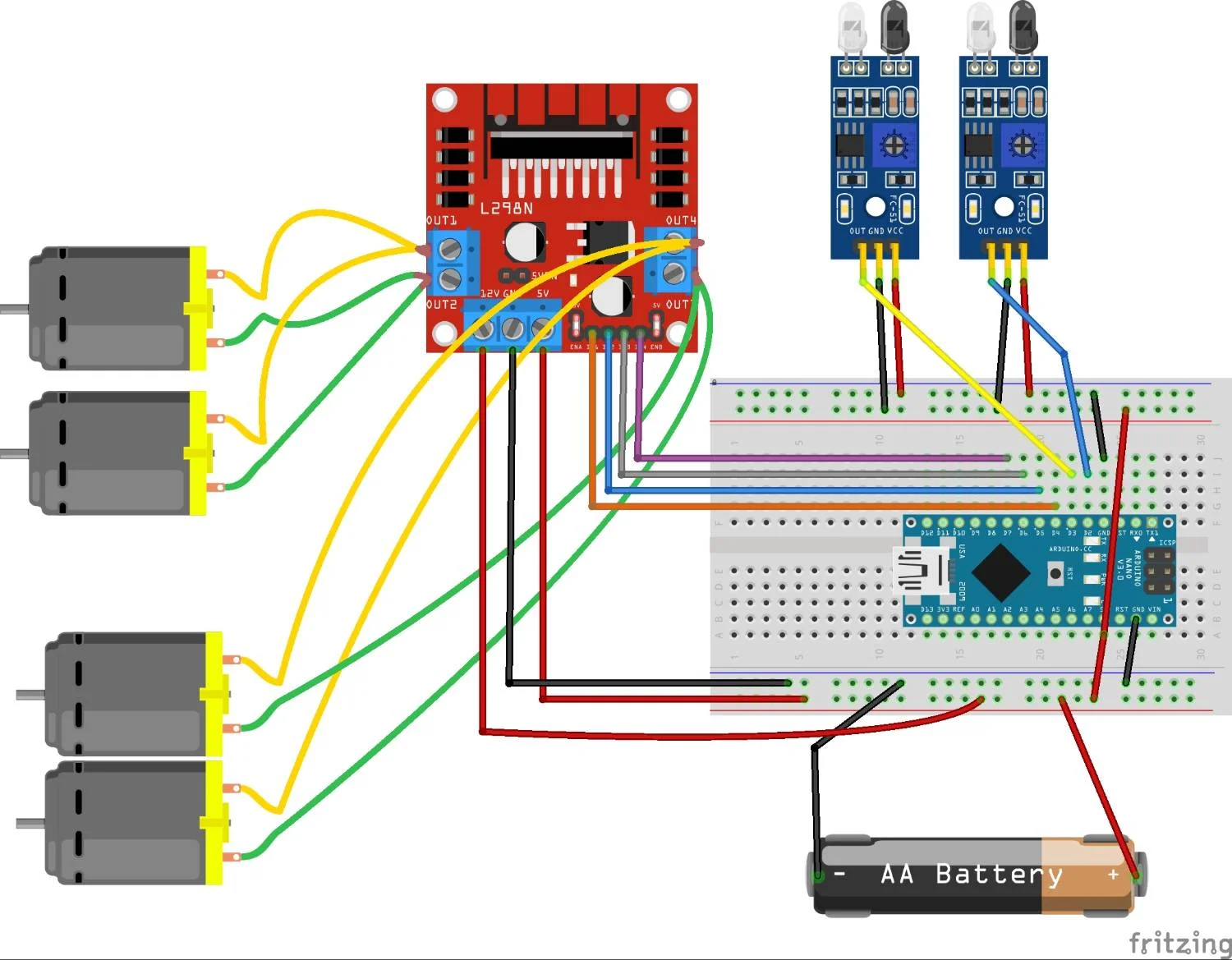
At the bottom, you can see the wiring schematic
Applications and Learning Outcome
This project is widely used in educational robotics because it introduces key concepts such as sensor integration, motor control, and decision-making logic. It also helps learners understand how real-time systems work.
Line follower robots are also used in industrial automation, warehouse transport systems, and autonomous navigation research.
By completing this project, you gain practical experience in:
-
Working with IR sensors
-
Controlling DC motors using a motor driver
-
Writing decision-based Arduino code
-
Understanding basic robotics navigation systems
Overall, this project is a strong foundation for more advanced robotics such as obstacle avoidance, maze solving, and autonomous navigation systems.
Be the first to receive professional and creative projects
Click the link 👇 below to download
Line tracking robot (4931 downloads )